
Reluctant to release models: There are many reasons designers are slow to hand over their model to aid the contractor. These may include:
- Loss of control in the set-out process
- Uncertainty on how quality control is guaranteed
- The contractor may use parts of the model for set-out, in ways it was not intended
- Concern it is opening the designer to unnecessary extra risk
- Lack of knowledge in the new technology – (we have not done it before)
- Concern in divulging intellectual property
These are all valid concerns and thus, need addressing.
Benefits to the contractor: What are some of the benefits to the Contractor / sub-contractor in using digital laser set-out?
- Minimise set-out (layout) time (Can be up to 34% less working hours)
- Minimise time delays (identification of unknowns before going into the field)
- Greater accuracy (± 7mm, compared with traditional means of ± 25mm)
- Minimise set-out mistakes (greater Quality Control processes)
- Significant reduction in on-site rework (resultant of above point 3 and 4)
- Cost savings (resultant of above point 1 and 5)
- Provision of future works and ability to efficiently generate accurate as-constructed models
- Increased safety (e.g.: minimise work at heights by installing ferrules to slab formwork before casting. Rework is typically high risk work, as it involves taking down equipment, and carrying out tasks in a: non-ideal order and environment. I have come across figures mentioned of; 40% of reported incidents on construction sites, occur during re-work operations)
The full benefit of comprehensive clash detection at construction stage may not eventuate if an accurate layout method is not employed.
Traditional paper set-out drawings: It appears as we further embrace computer technologies, many of the skills in documentation seem to be disappearing. The competence of producing dimensioned set-out drawings is one of these. In reading Architectural drawings today, it is easy to see how the builder is often confused. RFI’s (requests for information) over set-out queries are on the rise. These forms of drawing often contain comments such as “Do not measure/scale off drawings”. Unfortunately, it’s a poor cop-out if the drawing contains multiple deficiencies, or confusing/badly noted string dimensions. They are often not picked up, for example; until the carpenters are erecting the form-work with an immediate concrete pore ahead. Delays do occur due to bad documentation.
The task of quality checking paper set-out is not an easy one. The use of 3D models to generate the documentation does help, but is still does not resolve the documenter’s skill deficiency.
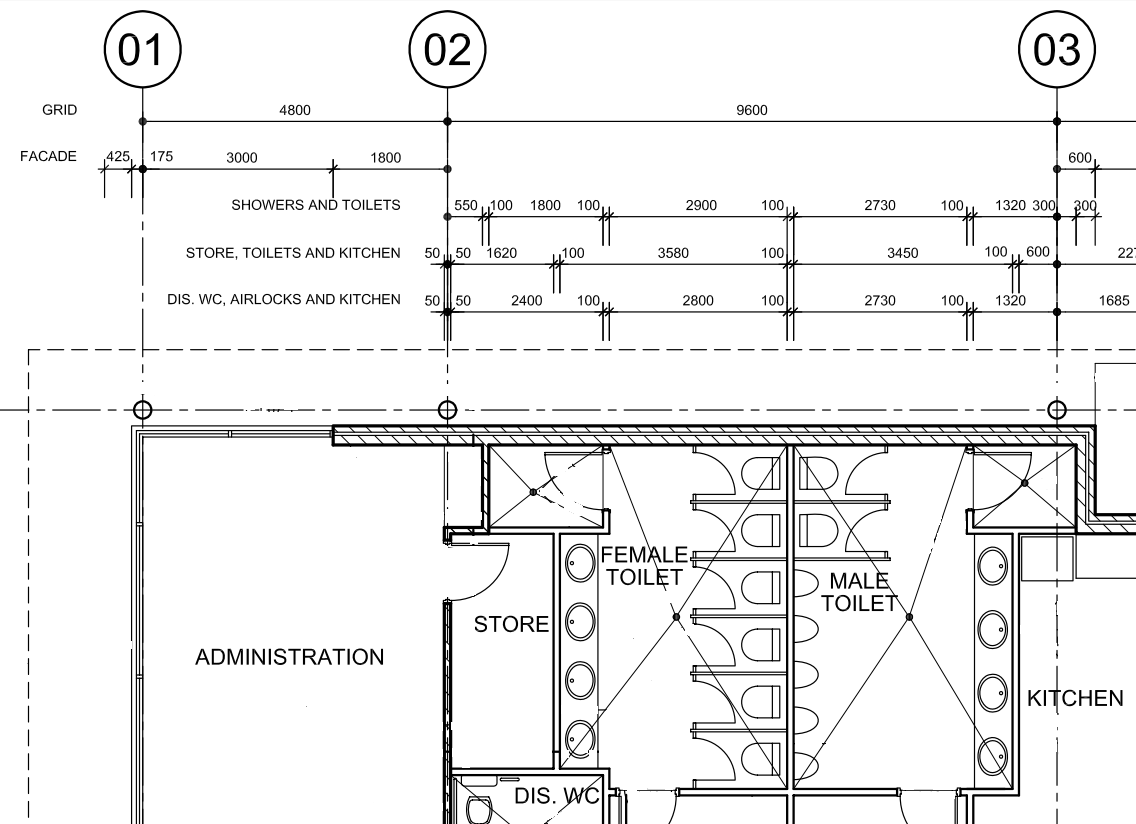
Above: part sample layout plan clearly identifying string dimensions
Construction Rework Figures: Available statistics on typical construction projects:
Reference; A Rework Reduction Model for Construction by Peter E D Love, Zahir Irani and David Edwards November 2004
In Australia, approximately 12% of a building constructions project cost is attributed to re-work. 6.4% in direct costs and 5.6% in indirect costs.
Breaking down the 12% of cost incurred:
30% design errors
46% construction execution
• Setting out errors
• Inadequate supervision
• Staff turnover
• Low skill error
24% other reasons
• Poor or incompatible materials
• Damage from other trades
• Weather damage
These figures will vary from project to project. It is influenced by job size and complexity. Large projects are typically more efficient while complex projects have a greater risk of errors.
Benefits to the Designer: The contractor is definitely the big winner when using a digital set-out directly from the model. So what does the designer gain from this new technology?
- A more accurate representation of design intent is achieved. Set-out errors often lead to poor architectural outcomes
- A reduction in last minute “request for information” (RFI) queries
- Deviations on site may be identified/reported earlier, and thus a better outcome is possible
- Complex designs are constructible. In complex designs, traditional paper set-out drawings may not adequately communicate the relevant information to the contractor
- If engaged appropriately risk is reduced – QC increased (See process below. Traditional paper set-out drawings are notorious for; lacking quality control, easy to miss-read and deficiencies)
- If engaged appropriately allows more efficient communication between the contractor and designer (See process below).
- Reduced time in documentation production. Every point on the drawing does not need detailed dimensions.
- If engaged appropriately quality control resourcing time is reduced (checking of drawings to make sure they adequately communicate the relevant information)
- Method promotes a reduction of cost over-runs; thus client perceives a greater service provided by the design team. Happy clients, leads to return business
BIM management plans and processes: The use of digital model set-out (layout) is not mentioned in any part of NATSPEC BIM guide. In-fact, from the BIM Management Plans (including execution plans) publically available, there is little mention of using CAD or BIM for building element set-outs. However I can’t see that lasting for long.
I have seen minimum quality control processes being engaged in this topic. I believe this may be due to lack of awareness of what is involved (the technology process and its capabilities), and risk incurred/avoided by the relevant parties.
With any new technology, it is just a matter of using it correctly and not letting the new tool get in the way of quality control. Below, I have developed a draft process to allow a structured, trackable and controlled data exchange. A derivative of this should help in alleviating the above concerns. It may seem over detailed; however it is faster and more reliable than traditional paper set-out means.
Model use for consultant set-out approval process:
Below is a draft process workflow. (The author does not take any responsibility of the below).

Contractor Steps:
C1. Requests set-out information for specific area from consultant:
The required area and components to be digitally set-out are identified, and a formal request is issued to the consultant. (Similar to traditional workflow processes)C2. Review drawings:
Received drawings (PDF format) are evaluated to decide if they are fit for construction. Mark-ups and comments added as required. Quick process turnaround required. (Similar to traditional workflow processes)C3. Is drawing fit for construction? (Gate)
Do drawings pass review process? Approve: Sign off and proceed to C4. Reject: Query issued back to A1.Approved drawings are used on site for communication, general discussion, identification of type information, specific component notes, and for checking purposes. (Similar to traditional workflow processes)
C4. Request Model;
3D model of approved components requested from the consultant.C5. Identifies set-out points in model;
Create 3D DXF set-out point file. Issue for checking;
“With-in the point creator authoring software”, the required set-out points are identified and tagged (semi-automated process). Points will include a prefix to identify component type and a sequential number (e.g. S05). Each point ID will be unique per floor level. Set-out points are exported as a 3D DXF (Drawing Exchange Format). These set-out points now become a set-out construction model, with the points given an LOD350 level of development (ref: BIMForum LOD Specification). The 3D DXF file is released to the consultant for checking (This DXF file is now seen as a shop drawing and typical processes ensue).
C6. Export points to field survey set-out tool;
C7. Set-out on site. Log report generated;
Points are set-out on site. A detailed log is kept of each set-out point including, time and date of layout, the set-up name, the operators name, tolerance information after the set-out for each point. The log is issued to parties involved (on the same day of the set-out). This is an official record for quality assurance and can be referred to in the event of a dispute.C8. Any deviations issued to Consultant (As-Built models);
Any set-out outside a predefined tolerance are highlighted, and this information is released back to the relevant parties (via DXF file) to record “Field Verified” (As-Built) drawings/model.Consultant Steps:
A1. Update and verify “requested set-out area” in model. Add model data attributes;
Following the request of a specific area needing set-out, the consultant thoroughly checks all data in components to make sure they are up to date and correct. The following component attributes are added:Date of verification/checking – ISO date format
Checked by: - Full Name
A2. Issue PDF drawings of requested area including some check dimensions. Issue for "construction approval"
PDF Drawing sheet of relevant area is released to the Contractor for “Construction Approval”. Drawings to include, all relevant notations, symbologies, types, code identification, penetrations, set-downs, centre lines of partitions and strategic check dimensions off grid, of “some” key items. Items outside the scope of set-out are identified. A reference to the location of this data is called up. (e.g. in a slab set-out the Architect may only be responsible to set-out the top of the slab. The set-out of the underside is a resultant of the slab thickness called up on the structural drawings.) (It is similar to traditional workflows with the exception of dimensions not included)NOTE: When using digital set-outs they are absolute coordinates. Thus the set-out to rule based items cannot be part of digital set-outs. Rules such as; “equal spacing”, or Minimum/Maximum distance off an existing item will not be part of the digital set-out scope.
A3. Export only relevant part of model including 3D levels & grids. Issues for "Set-out point identification":
Following approval, components attributed with relevant; “Date of Verification” and “Check by” is exported along with a 3D Levels and Grids to create a new: “Part Model”. This model is released to the contractor with the status of "Set-out point identification"(By exporting only the relevant area minimum intellectual property is lost.)
A4. Consultant overlays 3D DXF file into BIM & reviews:
Consultant receives a 3D DXF point file from the contractor. This is linked to the current model and over-layed. A visual/measured check is carried out to make sure design intent is met and set-out points are within the scope of the consultant’s responsibility. Quick process turnaround needed.A5. Do set-out points meet design intent? (Gate);
Points are rejected or approved. Rejected points with queries go to C5. Approved points are sent to C6. This step is seen in a similar light to how electronic shop drawing approval occurs with appropriate disclaimers included.A6. Deviations updated in model;
If an as-built model is a contractual deliverable: A 3D DXF file (locating deviations) is released to the consultant who links and overlays it into their model. Relevant model geometry updated.The above process is a potential starting point, and if it works well, could be compacted to combine step A2 and A3. The success of the process relies heavily on a quick turnaround on the checking steps.
NOTE: The use of the term “Consultant” in this article may include any design team member or sub-contractor.
The technology: The technology used in identifying the set-out points in the model is quite clever. It can be as simple as selecting a model object or type component, and it will automatically add the points to the corners, centre lines or grid intersections. Curved strings can have points identified at set intervals. Points are given sequential numbers including prefixes. In some cases data attributes can also be added. This automation greatly assists in minimising human error.

Above – Image of layout points in Autodesk Revit. These sample points were created in less than one minute.
Following the creation of set-out points, a report or DXF 3D CAD file can be easily generated. These can be used for checking and sign-off.

Above: Sample deviation report

On site a surveyor will have positioned key survey control markers. These are highly visible points, typically applied to concrete or block-work structures, including; cores, columns, sheer walls and adjacent buildings. The point creator operator can specify two of these control points in the point creator tool. The coordinates in the model, are thus transformed into the surveyors site geo-spatial coordinate system.
Following layout point completion, a log report may be downloaded to the application and a deviation report generated. Points outside the accepted tolerances may then be exported to a new DXF file and issued to the design consultants to update their model.
Applications: Recommended types of components to use this method of set-out are:
- Wall/partition set-outs
- Concrete plinths / piles
- Hydraulic service collars
- Penetrations
- Hangers for ductwork, pipework, cable trays etc.
- Threaded ferrule placement
Responsibility: Only elements within the responsibility of the relevant party are extracted from their model. The example above identifies a typical concrete slab layout. In Australia; the Architect is responsible to locate the: floor slab edge, set downs and major penetrations. The structural engineer takes the responsibility for the beam size and depth, and slab thickness. Concrete beam locations are a resultant of the grid lines and sab-edges. Thus data may need to come from two different parties in order to gain the entire set-out information. This is one reason why the checking and sign off part of the above procedure is needed.
Complex design: In moving forward, we are starting to see more and more circumstances where complex geometry designs are passed over to builders to construct. Traditional 2D paper drawings do not always adequately convey the relevant information for the builder to truly understand how to construct it. The use of digital set-out can be one method to set-out and maintain quality control. Thus as a designer, if you are creating these complex forms, shying away from this technology, will likely end up with poor quality outcomes.
Close: Digital set-out is going to become more popular as time goes on. Equipment will become cheaper and contractors will become more aware of it. If engaged properly the new technology can be a win, win for all involved. However, like anything, if not used appropriately there will be losers. The above identifies the significance of a documented process.
It is appropriate timing, as one of my fellow Melbourne BIM Bloggers (Practical BIM) has recently (April 2013) blogged on an issue he has come across on this subject. The similar posts are just coincidence. I've been researching this article for the past few weeks. If anything, it highlights the topic requires thorough discussion in the industry.
On any of my posts, I welcome comments and feedback. If anything, I know people are reading them, but more importantly; debate and counter discussion always improve methodologies.
References:
The above methods are in relation to Trimble Point Creator, being used along with the Trimble MEP solution. Efficiency figures are derived from here.
Other relevant reverences:
Penn Stage BIM Execution Planning reference to: 3D Control & Planning (Digital Layout) here:
Construction Business Owner: Making BIM Bigger - January 2014 - Cathi Hayes. here:
Plumbing Connection: Set out to be Accurate - here:
While entirely appropriate, I thought it ironic that you included a caveat on the use of your draft workflow for digital setout. Good article!
ReplyDeleteI can see the iterative issue of part models as something requiring some programmatic efficiencies. It would be nice if we could prevent snapping/measurement from all but selected elements - meaning recipients could see, but not snap/measure things not approved for setout.